Dense Stereo
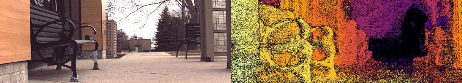
Dense stereo results from Bottlenose, in an outdoor setting. The camera uses Semi-Global Matching (SGM) and has tunable parameters such as subpixel, crosscheck, penalty, and number of directions.
Overview
Once calibrated, a Bottlenose Stereo camera can produce accurate dense stereo data.
Disparity Alignment
The Bottlenose stereo is a full 4K RGB-D camera. It performs a stereo matching between the left image (the source image) and the right image (the reference image) to compute a disparity value for each pixel of the source image. Thus, Bottlenose produces a disparity map that is always aligned with the image from its left image sensor.
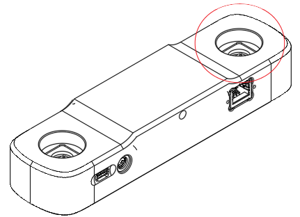
Left image sensor on a stereo Bottlenose camera. The disparity map is aligned with the left image.
Disparity Computation
Bottlenose computes a disparity using a hardware-accelerated implementation of the SGM (Semi-Global Matching) algorithm. This allows Bottlenose to expose interesting features such as cost computation with 4 or 8 paths aggregation, block size of up to 9x7 pixels, maximum disparity of 256 pixels and subpixel approximation. The resolution of the disparity map is determined by that of the input images.
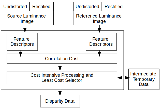
Block diagram of the stereo disparity map computation with Bottlenose
The disparity computation module assumes a pair of undistorted and rectified source and reference images as input. It then computes and matches a feature descriptor for each pixel. The disparity is the relative difference in the horizontal position of a point in the source image, which is searched horizontally in the reference image.
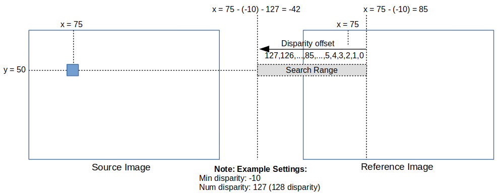
Bottlenose disparity search mechanism: although this shows a case where the search area spans outside the image, the effective search area is always up to the image boundary.
Bottlenose computes a correlation cost for each matching pixel and also evaluates the cost associated with the surrounding pixels (cost-intensive processing). The final disparity value is chosen to have the smallest cost value. This cost aggregate mechanism has the benefit of improving disparity accuracy while reducing mismatches and noise. Bottlenose can aggregate the cost from either 4 or 8 neighbouring pixels. For more details, refer to the SGM paper from CVPR2005.
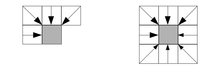
Cost Aggregation paths: for each pixel, Bottlenose performs either a 4-path or an 8-path cost aggregation
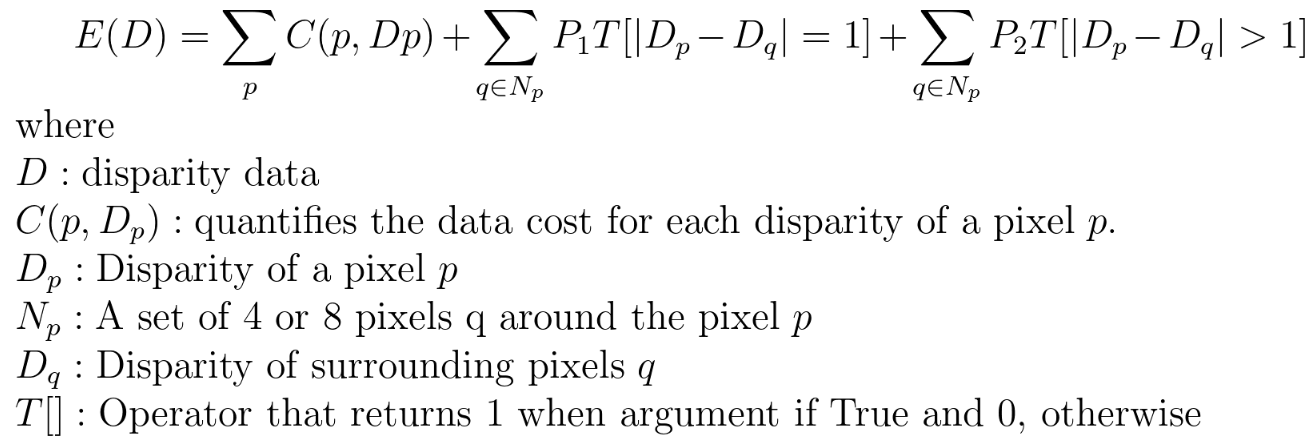
Bottlenose minimises the following energy function to select the best disparity for each pixel. In this formula, the penalty parameters, P1 and P2, are user-settable parameters.
Disparity Parameters
Bottlenose exposes a comprehensive list of settings that affect how the disparity map is computed. These settings are common SGM parameters and are located under the DisparityParameters section when accessed for instance with the Bottlenose Stereo Viewer application.
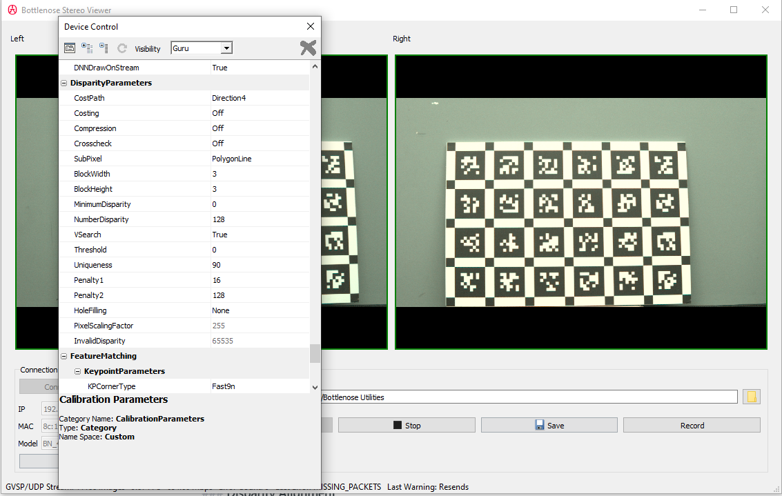
A screenshot of Stereo Viewer connected to a Bottlenose camera showing the Disparity Parameters.
Here is a description of the commonly used disparity parameters:
- CostPath: the disparity of a pixel is determined by referencing and propagating the costs of neighbouring pixels. Choose between
Direction4andDirection8to apply either a 4-path or 8-path cost aggregation scheme. - Crosscheck: if turned on, Bottlenose checks that each disparity calculated from the source image to the reference image matches the disparity from the reference image to the source image. This helps eliminate wrong disparities obtained, for example, when part of the source image is not visible from the reference image.
- SubPixel: allows subpixel estimation using either a polygon line fitting or a parabola fitting scheme.
- BlockWidth: the width of the block size from 0 to 4. The actual block width in pixels Bottlenose uses for processing is determined by the formula
ActualBW = BlockWidth x 2 + 1. - BlockHeight: the width of the block size from 0 to 3. Bottlenose determines the actual block height during processing with the formula
ActualBH = BlockHeight x 2 + 1. Thus, Bottlenose can handle block sizes of up to 9x7 pixels. - MinimumDisparity: sets the minimum disparity value from -127 to 127. This also allows the search range for the disparity to go from
MinimumDisparitytoMinimumDisparity + NumberDisparity. Bottlenose can therefore output a maximum disparity of 256. - NumberDisparity: the number of disparity steps is settable as a multiple of 8 from 32 to 128.
- Uniqueness: In areas with no texture, effectively determining disparity can be challenging as a clear correspondence between pixels may not be found. In this case, it is possible to output valid
disparity only when the ratio of the minimum cost to the next minimum cost is above a certain value. If the uniqueness ratio is set to 100, the disparity with minimum cost is always output. However, ifUniqueness < 100 and (minimum cost × 100) > (next minimum cost x Uniqueness)then the disparity is invalid. - Penalty1: this parameter ranges in values from 0 to 127 and controls the difference in disparity with surrounding pixels equals 1. A larger value makes the disparity data smoother with less change between values. We recommend setting Penalty1 as
Penalty1 ≤ (BlockHeight x 2 + 1) x (BlockWidth x 2 + 1). Thus, when for instance,BlockHeight = 3andBlockWidth = 4, the recommended setting for Penalty1 is in the range of 16 to 64. - Penalty2: this is the penalty parameter for when the difference in disparity with surrounding pixels is greater than 1 in the cost energy function. The value for Penalty2 is selected from
[0,511]. Penalty2 balances the smoothness introduced by Penalty1 and should always be set such thatPenalty1 < Penalty2. The rule of thumb is to setPenalty2 = 8 x Penalty1.
Disparity Mode
To put your camera into disparity mode, change the pixel format from YUV422_8 to Coord3D_C16. This can be done with any Gige Vision-compliant utility. The following steps show how to do this with the Bottlenose Stereo Viewer or the eBusPlayer application.
- Connect to the camera with either
Stereo Vieweror theeBusPlayer - Click on
Device Control - Navigate to
ImageFormatControl- Change
PixelFormatfromYUV422_8toCoord3D_C16 - Make sure the offset parameters (
OffsetX,OffsetY,OffsetX1,OffsetY1) are set to values used during calibration
- Change
- Navigate to
ImageunderSensorsto set bothUndistortionandRectificationtoTrue. This may requireVisibilitymode be set toGuru. Also, this assumes that proper calibration parameters have been loaded onto the camera. Refer to our calibration page for details on how to calibrate your camera and to the calibration parameters page to learn about the different ways to upload your calibration parameters.
At this point, your camera should be streaming disparity maps. You will then need to navigate to DisparityParameters to change default settings as needed.
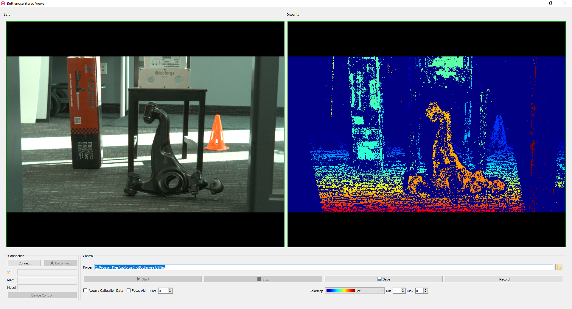
Disparity images can be visualised as a grey image inside your eBUSPlayer. The Bottlenose Stereo Viewer utility can colour code the disparity image.
The disparity image is computed for the set image resolution. For a different resolution, stop streaming and change the Width and Height under ImageFormatControl.
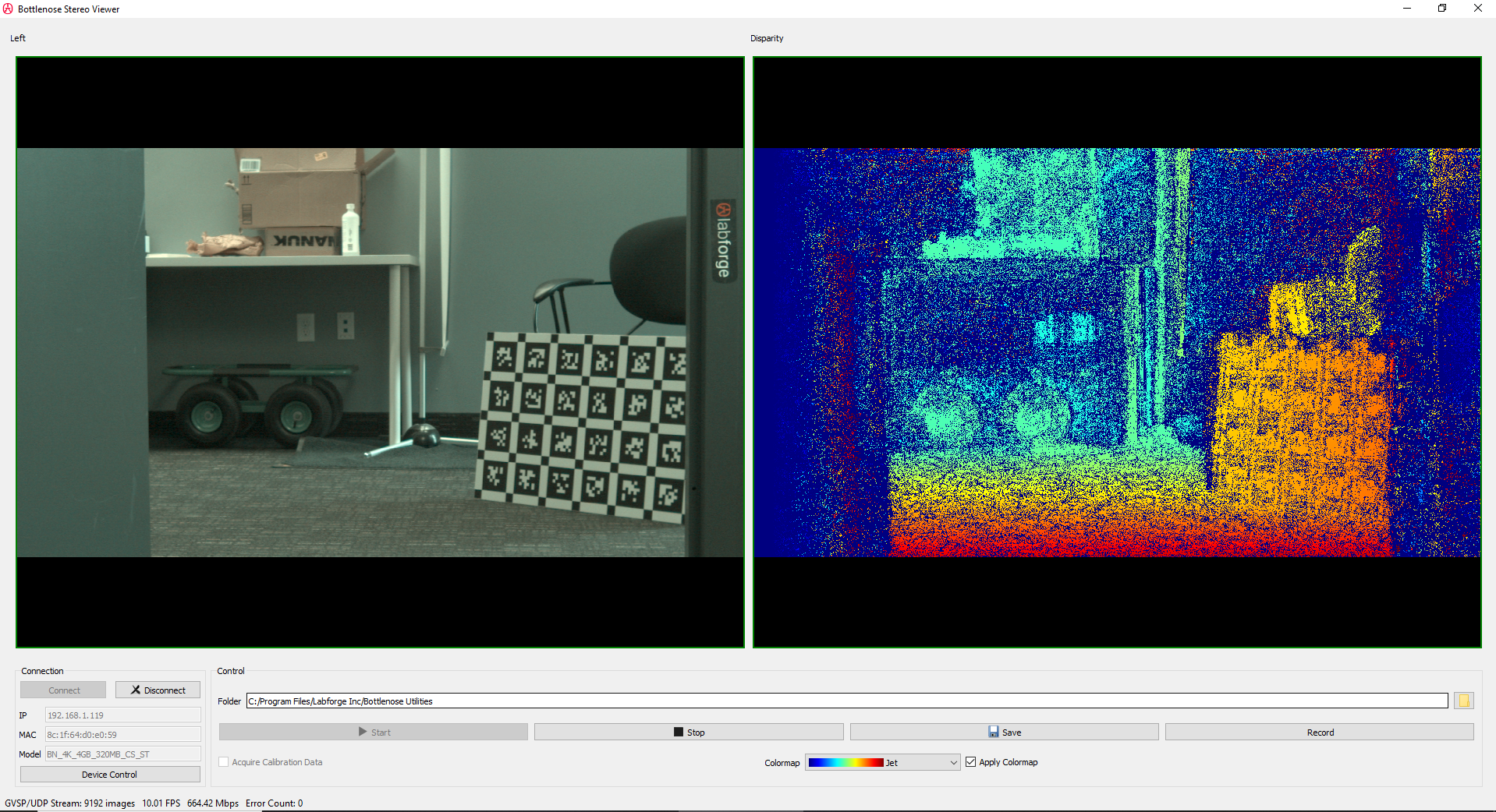
A screenshot of Stereo Viewer displaying a disparity map with the corresponding left image
Disparity Processing
The disparity map computed by Bottlenose represents the unsigned offset value from the minimum disparity. Bottlenose encodes each disparity value as a 16-bit fixed point decimal. Invalid disparities are set to a special value of 65535, which can also be accessed from the register InvalidDisparity. Before any meaningful computation, the disparity map must be converted into floating-point with the following equation:

The scaling factor is set to 255 and can be directly obtained from the camera register PixelScalingFactor. Similarly, the minimum disparity used for computation is exposed by the camera register MinimumDisparity.
A disparity map can further be processed to generate a depth map or a point cloud using 3D triangulation. When saving disparity, the Bottlenose Stereo Viewer application can also save a corresponding point cloud file in a PLY format. The file can be viewed using tools such as MeshLab.
A scene with corresponding disparity
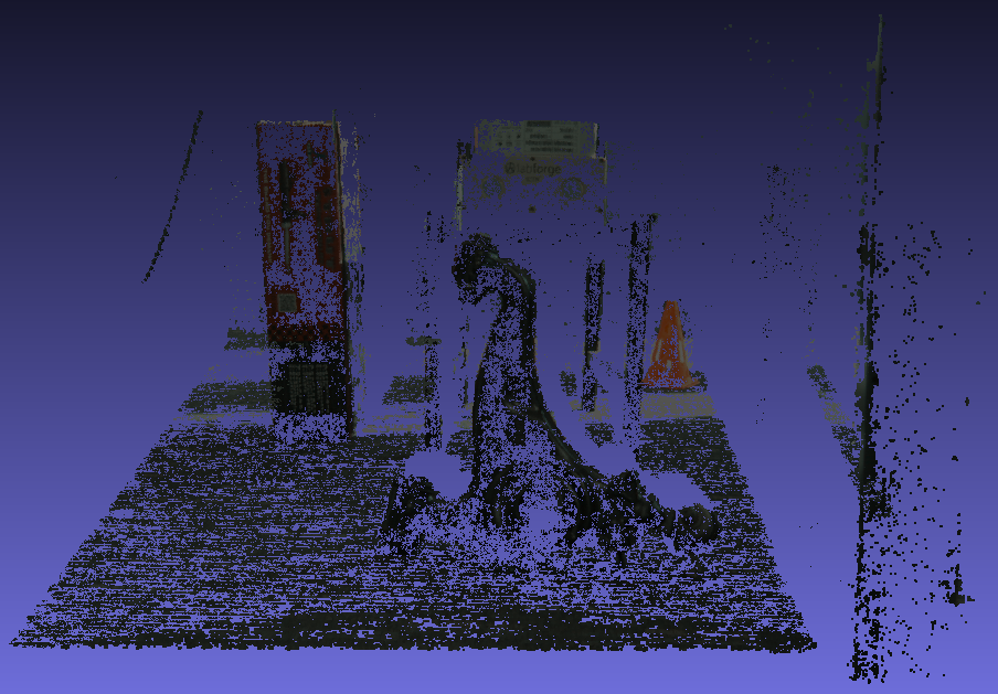
A point cloud of the above scene is viewed with MeshLab.
Disparity with Python
Python can be used to stream disparity maps from a stereo Bottlenose camera. For details on how to perform this, refer to our sample code.
The following code snippet describes how to turn on disparity on a stereo Bottlenose camera from Python. This code assumes the camera has the proper calibration data and image settings.
# Get device parameters from the Gige Vision device
device_params = device.GetParameters()

# Enable multipart if you want to receive left image and disparity
multipart = device_params.Get("GevSCCFGMultiPartEnabled")
multipart.SetValue(True)

# Turn on rectification
rectify = device_params.Get("Rectification")
rectify.SetValue(True)

# Turn on undistortion
undistort = device_params.Get("Undistortion")
undistort.SetValue(True)

# set camera into disparity mode
pixel_format = device_params.Get("PixelFormat")
pixel_format.SetValue("Coord3D_C16")
Once the camera is in disparity mode, every buffer it exchanges with the receiving application will contain a disparity map aligned to the left image. If multipart is not turned on, the camera will only stream the disparity image. The disparity map is encoded as scaled 16-bit integers. Disparity that are invalid are set to 65535. The map should be divided by the scaling factor to obtain subpixel information. The following sample code shows how to decode the disparity map.
# Get device parameters from the Gige Vision device
device_params = device.GetParameters()

# obtain scaling factor
pixel_scaling_reg = device_params.Get("PixelScalingFactor")
scaling_factor = pixel_scaling_reg.GetValue()

# Obtain invalid disparity marker
invalid_disparity_reg = device_params.Get("InvalidDisparity")
invalid_disparity = invalid_disparity_reg.GetValue()

while True:
   # Retrieve next pvbuffer
   result, pvbuffer, operational_result = stream.RetrieveBuffer(1000)
   if result.IsOK() and operational_result.IsOK():
      payload_type = pvbuffer.GetPayloadType()

      # only disparity is transmitted
      if payload_type == eb.PvPayloadTypeImage:
         disparity = pvbuffer.GetImage()
         disparity_data = disparity.GetDataPointer()
         print(f" dW: {disparity.GetWidth()} dH: {disparity.GetHeight()} ")

      # disparity and left image transmitted
      elif payload_type == eb.PvPayloadTypeMultiPart:
         image = pvbuffer.GetMultiPartContainer().GetPart(0).GetImage()
         disparity = pvbuffer.GetMultiPartContainer().GetPart(1).GetImage()
         image_data = image.GetDataPointer()
         disparity_data = disparity.GetDataPointer()
         # invalid disparity values should be equal to invalid_disparity = 65535
         # divide data by scaling_factor to obtain subpixel
         print(f" iW: {image.GetWidth()} iH: {image.GetHeight()} ", end='')
         print(f" dW: {disparity.GetWidth()} dH: {disparity.GetHeight()} ")

      # post-process disparity map
      # invalid disparity values should be equal to invalid_disparity = 65535
      # divide data by scaling_factor to obtain subpixel
Updated 8 months ago