Computer and Network Adapters
For optimal performance, please follow the below guide.
This guide describes how to optimize network interface cards (NIC) for optimal performance with the Bottlenose Camera and its SDK.
Network Interface Card (NIC) Selection
Bottlenose uses Pleora eBUS Universal Pro as the transport layer for GigE communication. Most 1GigE NICs and switches are compatible with this. We highly recommend following this guide to configure your network adapter for optimal performance.
In addition to that, we highly recommend using Intel-based network adapters for communicating with Bottlenose. Many other consumer-based network adapters commonly found in laptops may not support the reconfigurability outlined in the above guide. This applies to features like interrupt moderation, Jumbo packet support, or transmit and receive buffer provisioning. Please see the list below for Labforge-tested adapters:
Labforge-tested Ethernet adapters:
- Intel Pro 1000
- Intel I219
Known Problems:
- Realtek RTL8111/8168/8411: Does not support configuring interrupt moderation settings on Linux systems. These devices have poor performance in combination with the eBUS Pro Universal driver on Linux.
Further, we advise against using USB-to-Ethernet dongles for communicating with Bottlenose as the USB device management introduces unnecessary latencies that can degrade the network performance.
Enabling Jumbo Frames
For better performance, we recommend enabling Jumbo Frames on your network and setting your NIC minimum transfer unit (MTU) to at least 9000 bytes. To do so, follow these steps. This is a one-time setup.
Microsoft Windows
- Close any existing camera sessions. Example eBUS Player or the Labforge Bottlenose utility apps.
- Open the Network and Sharing Center.
- Click Change adapter settings.
- Right-click the network for which you want to enable jumbo frames and select Properties.
- Under the Networking tab, click the Configure button for the network adapter.
- Select the Advanced tab.
- Select Jumbo Frame and change the value from
disabledto9,014bytes or to9KB MTU, depending on your system. - Click OK to save and close the windows.
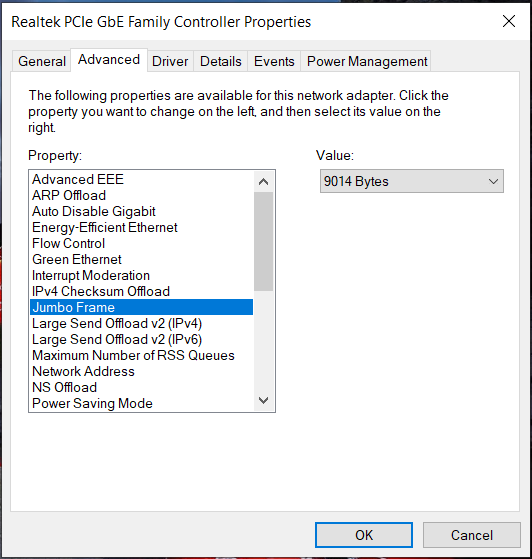
Network Properties Window showing the Jumbo Frame set to 9,014 Bytes.
Ubuntu Linux using Network Manager
- Click on the Network Manager Tray Icon, select
Wired Connected - In the
Networkproperties configure the chosen interface - On the
Identitytab you can manually enter the MTU, a value of9000is recommended. - Once Applied the profile should be persistent between reboots for the chosen interface
Linux using Command Line
- Open a terminal
- Assuming Bottlenose is connected to the interface
eno1, configure the interface usingifconfigas follows
sudo ifconfig eno1 mtu 9000
# Check that the mtu was applied
ifconfig eno1
# Expected output should highlight an mtu of 9000 or more
eno1: flags=4163<UP,BROADCAST,RUNNING,MULTICAST>  mtu 9000
        inet 169.254.6.67  netmask 255.255.0.0  broadcast 169.254.255.255
        ether 70:85:c2:8f:e8:36  txqueuelen 1000  (Ethernet)
        RX packets 6712  bytes 2135804 (2.1 MB)
        RX errors 0  dropped 0  overruns 0  frame 0
        TX packets 3735  bytes 445236 (445.2 KB)
        TX errors 0  dropped 0 overruns 0  carrier 0  collisions 0
device interrupt 16 memory 0xa3200000-a3220000- The MTU setting is transient and has to be set this way each time the machine reboots. If the interface is also managed by Network Manager or a similar tool, changing the interface profile may invalidate the MTU setting too.
Multi-Camera NIC Configuration
When using a switch with multiple GigE Vision cameras, please reduce the GevSCPSPacketSize and increase the GevSCPD. The reduced packet size and increased delay help to remove packet resend requests in a multi-camera network environment. Please ensure that you configured your NIC minimum transfer size large enough to accommodate the chosen GevSCPSPacketSize, as described here. For multi-camera configurations, we refer to the following resources:
- Connecting Multiple Cameras to a Single Ethernet Port
- Setting up Multiple GigE Cameras
- Using Inter Packet Delay with GigE Cameras
- Use of GigE Vision Ethernet Cameras for Flight test Applications without Data Loss
As a working example, for two Bottlenose cameras at a 1080p resolution, connected via a switch to a single 1Gb/s NIC, a packet size of 4,000 bytes and packet delay of 400 nanoseconds is a good setting. This configuration results in no to minimum packet loss and resend attemps.
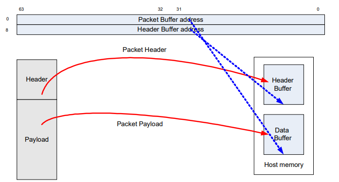
Further, if your NIC supports packet splitting in hardware, like the Intel x550 chipset, please enable that in hardware. This will reduce the CPU load on the host PC.
Stereo Viewer and eBus Player
GevSCPSPacketSize and GevSCPD are part of the Device Configuration and can be set via Device control. To view multiple Bottlenose cameras you can start multiple instances of each tool.
Python
Both parameters are exposed as integer values as part of the device handle and can be set as follows. An example for GevSCPSPacketSize is shown below.
device_params = device.GetParameters()
packet_size = device_params.Get("GevSCPSPacketSize")
res = packet_size.SetValue(value)
res, value = packet_size.GetValue()
if not res.IsOK():
	# Error handling
ROS2
Both parameters can be set via the ROS2 command line when the driver starts. To auto-negotiate the packet size between Bottlenose and your system set GevSCPSPacketSize to 0. Please note if GevSCPSPacketSize has been previously configured by any tool or that previous configuration is used as a ceiling for the size auto-negotiation.
ros2 run bottlenose_camera_driver bottlenose_camera_driver_node --ros-args \
	...
  -p GevSCPSPacketSize:=4000 \
  -p GevSCPD:=1500
To interface multiple Bottlenose cameras on a ROS2 system you can start multiple instances of the driver via the command line or a launch file. Each instance identifies the target camera by a MAC address. For each instance, we recommend renaming the driver node or its namespace to have separate publishing topics for each node, as described here. An example is shown below that places the first camera in namespace cam0 and the second camera in the namespace cam1.
ros2 run bottlenose_camera_driver bottlenose_camera_driver_node --ros-args --remap __ns:=/cam0 \
	-p mac_address:="<mac of first camera>"

# In a different terminal
ros2 run bottlenose_camera_driver bottlenose_camera_driver_node --ros-args --remap __ns:=/cam1 \
	-p mac_address:="<mac of second camera>"
...
Time Synchronization
Bottlenose supports synchronizing to external time sources via the Precision Time Protocol (PTP) and the Network Time Protocol (NTP). To mitigate conflicts between different time sources NTP support is disabled on the device by default.
Because external time synchronization changes the system time. Bottlenose may disconnect due to timeout at the time the first synchronization to the external clock source.
Timestamp
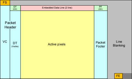
The timestamp encoded as frame time is the point in time when the complete frame was received by the image sensor. That event is triggered by the reception of the Frame End Packet (FE) from the image sensor. Please see below.
Precision Time Protocol
Bottlenose cameras support the Precision Time Protocol (PTP) per IEEE1588-2008. Resources to set up a local Grandmaster clock on a Linux system can be found here. For Bottlenose to synchronize via PTP you need to have at least one PTP grandmaster clock in your subnet. You buy a commercial clock source or set up a Linux machine that provides the grandmaster clock by installing ptpd. Windows 10 has native PTP support since 2018 you can find resources to set up PTP synchronization on a Windows system here.
Network Time Protocol
Bottlenose cameras support accepting UDP NTP time broadcasts. Because Bottlenose supports link-local addressing (LLA), the dynamic host protocol configuration protocol (DHCP) and fixed-IP addressing, there is no consistent mechanism for resolving an NTP server during network setup. As such, Bottlenose can only be configured to accept broadcasts from time sources. We provide an example configuration for NTPd here that broadcasts the time on the LLA range. If you are not using LLA (e.g. Bottlenose is directly plugged into your system's Ethernet port), change the broadcast parameter to the subnet that Bottlenose and your machine are connected to. If you want to use an upstream NTP server to synchronize your NTPd instance, adjust the parameters server and fudge accordingly.
Enabling NTP Broadcast Reception
In eBusPlayer and Stereo Viewer accepting NTP broadcasts to adjust calendar time can be enabled by setting ntpEnable to true from the Device Configuration menu.
The ROS2 driver can be configured to accept NTP broadcasts by setting the ntpEnable parameter during startup.
ros2 run bottlenose_camera_driver bottlenose_camera_driver_node \
  ...
	--ros-args -p ntpEnable:=true
Make sure you do not have competing PTP and NTP time sources on the same network that Bottlenose is running on, when NTP broadcast reception is enabled.
Using Calendar Time in Frame Timestamps
The GigE Vision Protocol uses a monotonic device clock to encode timestamps by default. There is no guarantee that the timestamp corresponds to the Calendar Time adjusted by PTP or NTP.
To remedy that, we support sending the calendar timestamp via GigE Vision Chunk Data. The timestamp we include is the number of milliseconds since the epoch: January 1st, 1970 at 00:00:00 UTC. If Bottlenose cannot synchronize to any external time sources it will maintain a timestamp starting in the year 2018.
The Stereo Viewer utility will automatically decode these chunks and use them as reference time for recorded filenames. The Bottlenose ROS2 driver automatically uses the device's calendar time for frame timestamps that are communicated on the ROS2 message bus. Currently, we do not have a working Python SDK example of how to evaluate calendar timestamps.
Updated 9 months ago