Stereo Calibration
Prerequisite
Calibration Target
Calibration targets come in various sizes and shapes. However, checkerboard and Apriltag targets are commonly used. The choice of a target will depend on the support from the calibration software package you are using. For each target, you will need to have basic knowledge such as the number of rows and columns, and the size of each cell that makes up the target pattern.
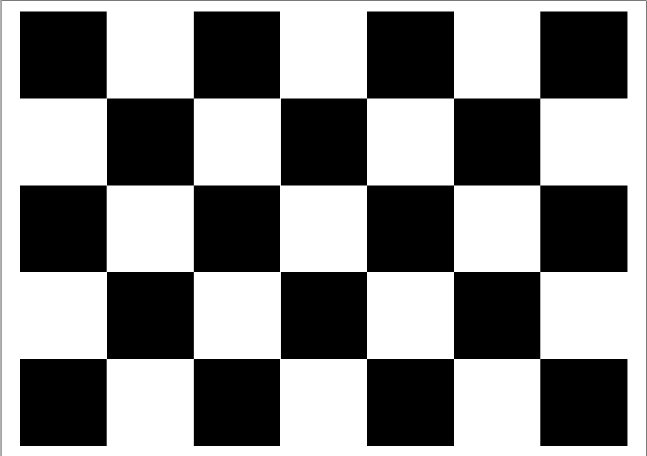
Example of a checkerboard calibration target: each cell is 40mm x 40mm square.
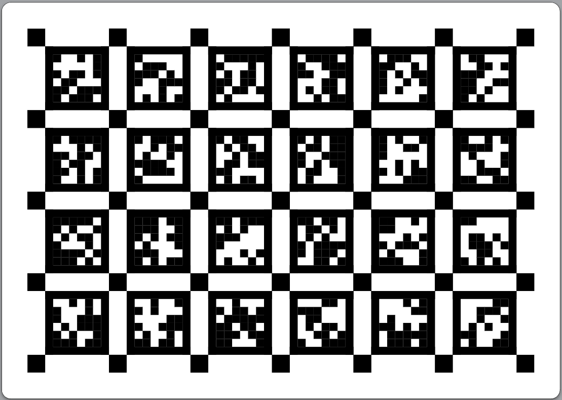
An Apriltag calibration target with 6 columns and 4 rows, each tag is 90mm with 25mm spacing.
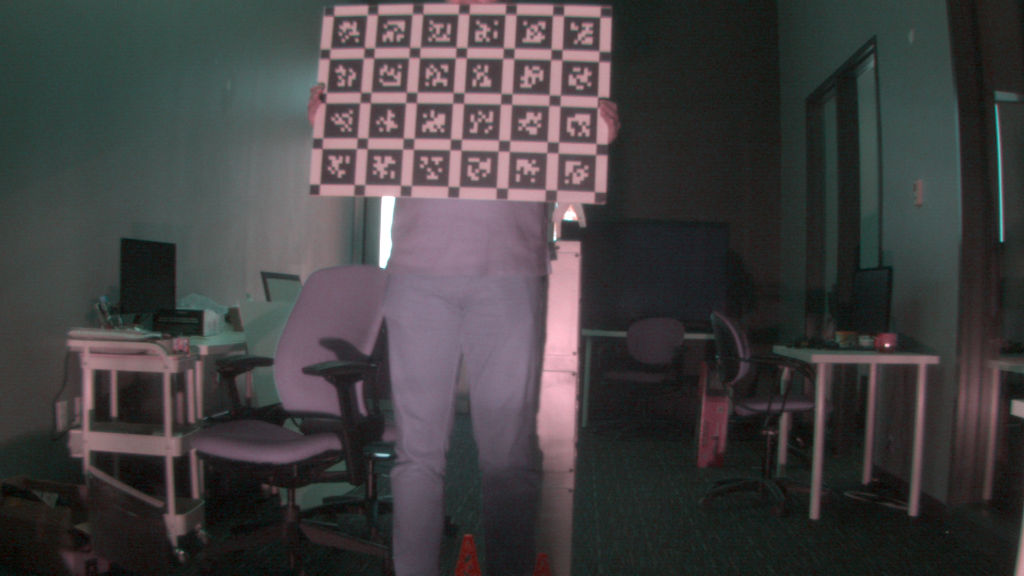
Targets and camera must be stationary for an accurate calibration during image capture. Targets must cover a large part of the image and the dataset should have a diversity of angles. Even though images below show targets being held in hand, this is not best practice and will result in poor calibration.
Image Quality
Data acquisition is the first step of the calibration process. Bottlenose cameras can be configured to stream images at different resolutions. Before calibration, make sure you have
- Install and focus your lenses to the same depth as your calibration target. Your calibration target should cover about a third of your field of view in each image.
- Set the lenses to the widest possible aperture.
- Select the resolution that you want to calibrate for.
- Enable auto white balance to optimize the contrast of your calibration target.
- Set the gamma correction to a minimum
1.0 ... 1.6. - Set gain to unity (
1.0), to avoid recording noise that could affect the accuracy of the calibration. - Set the exposure to avoid bleeding between the bright and dark features of your calibration target.
Calibration is lens-dependent. This means the camera has to be re-calibrated if the lenses are changed or refocused. Bottlenose does not ship with any lens but supports various off-the-shelf lenses. Lenses should be selected based on the application requirements.
Please calibrate once a desired resolution is selected. You will have to recalibrate when resolution and lenses are changed.
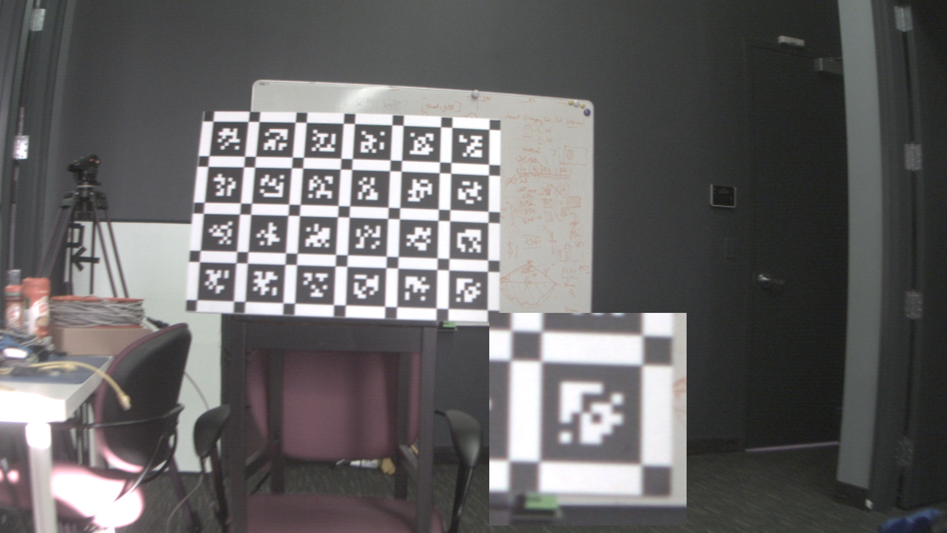
Collect about 10 pairs of good-quality images, which have the calibration target in full view in various sectors of the image. Only take as many images as you are willing to to inspect manually for the above characteristics. An example of a good calibration image is shown below.
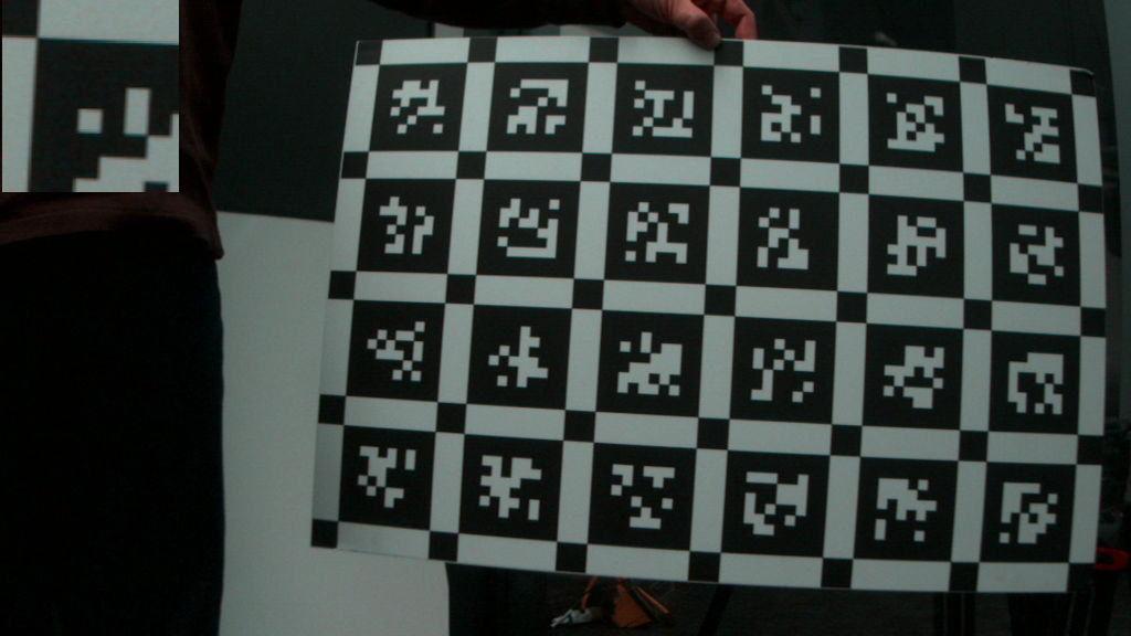
Good Calibration Image.
Target Covers More Than 1/3 of the Image.
Highlight Shows High Contrast and No Color Bleed in Target Corners.
Common Calibration Mistakes
See a collection of images below that highlight common calibration pitfalls.
The image below shows a too-small calibration target relative to the field of view (1). This may result in an expanded reprojection error and result in poor stereo and sparse point cloud performance. The operator should position the calibration target closer to the sensor, or invest in a larger calibration target for the desired application depth. Further, the contrast of the bright and dark corners of the calibration target is poor this is due to too narrow aperture settings (2) or too low exposure (7).
Lens Aperture SetToo Narrow, Calibration Target Coverage Too Small.
The image below also shows poor contrast between the white and the dark features of the calibration target (highlight emphasized), which is the result of a large gamma correction (5) and too high exposure or gain settings (6, 7).
Poor Calibration Target Contrast from Improper Gamma, Gain, or Exposure Settings
Image Offset
Bottlenose has on-camera compute for rectification that aligns the images along epipolar lines. This process uses calibration results uploaded by the user. However, before this calibration, the user also has the opportunity to manually offset the images to be better aligned. This is possible as the sensors are 12MP and we only use at most 8MP, allowing the user to digitally move the 'active image region' within the background 'canvas'.
Setting a Y1 offset correctly is currently mandatory for sparse stereo. Dense stereo does not need this and already has a working rectification pipeline. Once the sparse stereo pipeline includes rectification, we will remove the mandatory requirement for the Y1 offset. Nevertheless, its a good practice to start with optically aligned images on the vertical axis.
The left and right images may be not row-aligned. To mitigate this issue, Bottlenose exposes offset parameters. These parameters are OffsetY and OffsetY1 located under ImageFormatControl of your device control. We recommend to only modify **OffsetY1**. Change OffsetY1 until the right image appears row-aligned before acquiring data for calibration in the center of the image.
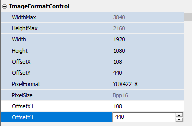
Device Control Showing Image OffsetY1 Parameter.
You can use the ruler and zoom functions of the Stereo Viewer to help with that. Any valid row number in the image will project a 3-pixel wide line in both images. Set this line row close to the center of the image to match up the left and right features of the scene while setting the OffsetY1 parameter. The image below shows the view of the stereo viewer of a zoomed-in target in both images with the ruler shown before the proper offset is set.
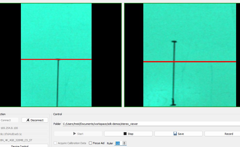
Stereo Viewer Showing Ruler Set to Image Row 550 before Offset Correction
The following image shows the same scene and zoom after setting the proper value for OffsetY1.
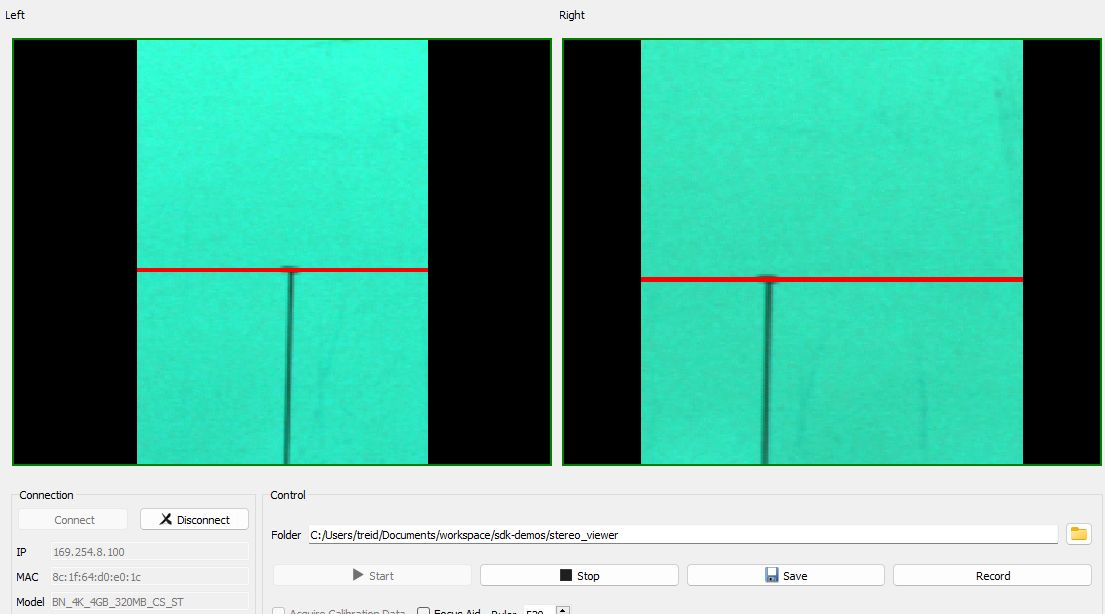
Stereo Viewer After Setting The Proper Offset
When the camera is calibrated with a given offset, the same offset value should be used later on for sparse 3D or dense stereo.
See Imaging on how to apply this parameter in the Python SDK and our ROS2 driver. The parameter setting does not persist between power-ups of the camera and has to be set each time the camera is rebooted.
Data Acquisition
Any GigE Vision-compliant tool can be used to capture data from a Bottlenose. If using the Bottlenose Stereo Viewer utility, you can acquire calibration data with the following steps.
- Launch the Stereo Viewer utility
- Click on
Connectto connect to your Bottlenose camera. - Make sure the
Acquire Calibration Databox is selected. This tells the Bottlenose camera to disable undistortion and rectification from the image acquisition pipeline. - Click on the folder selector to set the data folder to your desired location. The utility will automatically create two subfolders
cam0andcam1to store images from the left and right camera respectively. - Make sure the offset
OffsetY1parameter is set to what was determined in the previous step. - Click on the
Startbutton to start the acquisition process. - Click the
Savebutton for every pair of images you would like to save. You can always use theRecordbutton instead to continuously save images. Images acquired for calibration must include a calibration target.
To optimize write-rates for continously saving images:
- make sure you have enough space on your machine,
- and exclude the target calibration directory from Microsoft Defender or your chosen Antivirus program to ensure fast write rates.
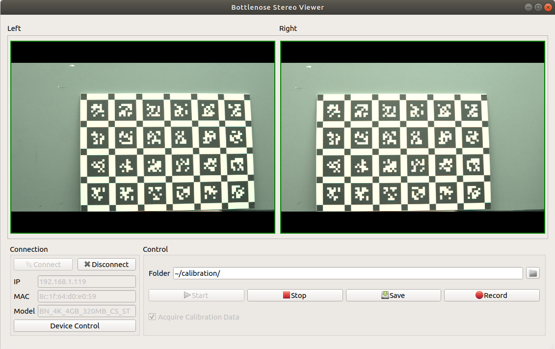
A screenshot of the Bottlenose Stereo Viewer image acquisition tool.
Calibration Process
The calibration process consists of feeding the calibration images into a calibration tool such as calib by calib.io to generate intrinsic and extrinsic parameters for the camera.
Pinhole Model
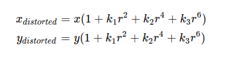
Bottlenose supports the pinhole camera model taking into account the radial and tangential distortion factors. Radial distortion causes straight lines to appear curved. Radial distortion becomes larger the farther points are from the center of the image. Radial distortion can be represented as follows:
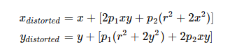
Similarly, tangential distortion occurs because the image-taking lens is not aligned perfectly parallel to the imaging plane. So, some areas in the image may look nearer than expected. The amount of tangential distortion can be represented as below:
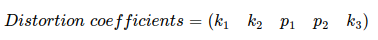
To remove distortion from images, Bottlenose requires the following five parameters that constitute the distortion coefficients:
Intrinsic and Extrinsic Parameters
Once calibrated, the intrinsic and extrinsic parameters along with the distortion coefficients can be uploaded into the camera. The intrinsic parameters include the focal length and the optical center of the camera and help in removing lens distortion. The extrinsic parameters contain the rotation and the translation vectors of the camera and help translate the coordinates of a 3D point to a coordinate system. Bottlenose uses these parameters to internally compute its undistortion, rectification, and 3D reprojection parameters. After calibration, Bottlenose will be able to produce undistorted and stereo-rectified images.
See the calibration parameter settings on how to apply these parameters via the GigE Vision Interface or Bottlenose Utilities.
Sample Calibration Session Using Calib.io
After the dataset has been acquired various tools can be used to compute the above calibration parameters. We show a sample approach here.
-
Start your calibration utility, assign the images for the camera pairs using
Set Images. For the Stereo Calibration please click onAdd Camerato add the second set of images.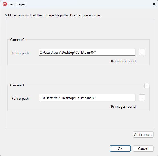
-
Once the pairs are loaded, click on
Detect Featuresto detect the features of the calibration target. Note that the parameters shown vary depending on your choice of calibration target and must to be accurately set to obtain a valid calibration.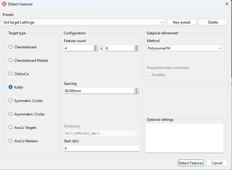
-
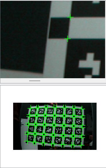
After the features have been detected, inspect each pair for the proper corner locations of the detected features. Exclude any pair of images (checkbox) where only a subset of the features are detected. If the corners show insufficient contrast and the center point of the detection is fuzzy, repeat the Image Quality tuning above. An example of a spot inspection is shown below.
-
After the set of good pairs has been selected, compute the calibration parameters by selecting
Optimize Camera(s). A sample of the settings is shown below. Please selectIndividual camera models,Optimize target geometry,999iterations, the function tolerance to0 %to avoid prematurely model selection, unsetonly decreasing steps, setestimate reprojection error, and setestimate covariance. For each camera selectOpenCVcamera model and leave the defaults checked.Depending on the chosen lens different model initializations can be selected. For the Raspberry Pi PT361060M3MP12 lens we recommend
Fisheye. For other lenses, different initializations may be more suitable. A non-convergence error from the utility is usually a sign that the initialization may not have been appropriate.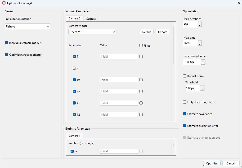
-
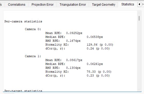
After the optimization has converged. Inspect the statistics pane for the quality of the calibration parameters. Each camera should achieve a median reprojection error of sub 0.1 pixels. If the median RPE exceeds this significantly the source of error is likely poor image quality or an unfocused lens.
-
Select
Calibration->Export Calibrationparameters and save the parameters. See this section on how to transmit these settings to the sensor.
Further References Aiding Calibration
Updated 8 months ago