Calibration Parameters
Overview
Once calibrated, the generated calibration parameters can be uploaded onto the Bottlenose camera for image undistortion, rectification, and 3D estimation. The calibration parameters for each image sensor inside a Bottlenose consist of the following values:
- Horizontal focal length, fx:
- Vertical focal length, fy: in general, fy is equal to fx.
- Horizontal optical center, cx
- Vertical optical center, cy
- Radial distortion parameters, k1, k2, and k3
- Tangential distortion parameters, p1 and p2
- Relative rotation vector, rx, ry, and rz
- Relative translation vector, tx, ty, and tz
- Calibrated image width and height.
Relative Rotation and Translation
Given a stereo setup, calibration software will choose one of the cameras as the origin. The calibration process generates a relative rotation R and a relative translation T between the cameras. Bottlenose always assumes its left camera to be the origin and will align its disparity and depth maps to this camera. The origin also known as the reference camera has its rotation and translation set to zeros.
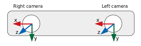
Bottlenose stereo camera coordinate systems. View from the front.
The relative rotation R is a 3x3 matrix that describes the rotation from the coordinate system of the left camera to that of the right camera. It's often referred to as the rotation matrix between the two cameras. The matrix R is useful for transforming points from one camera's coordinate system to the other camera's coordinate system. Therefore, R defines how the coordinate system of the right camera is rotated relative to the coordinate system of the origin, the left camera.
The relative translation T is a 3x1 vector representing the translation from the right camera's coordinate system to the left camera's coordinate system. It specifies the position of the left camera's optical center relative to the right camera's coordinate system.
Together, R and T bring any point given in the coordinate system of the left camera to a corresponding point in the coordinate system of the right camera. In more technical terms, the tuple of R and T performs a change of basis from the left camera's coordinate system to the right camera's coordinate system. Due to its duality, this tuple is equivalent to the position of the left camera relative to the right camera's coordinate system.
Bottlenose only accepts rotation vectors as input, and therefore cannot directly use a rotation matrix R. A 3x1 rotation vector can be obtained by applying the Rodrigues function to a 3x3 rotation matrix.
Bottlenose only accepts rotation vectors as parameter. If not supported by your calibration software, rotation matrices most be converted before uploading into the camera.
Setting Camera Parameters
Calibration parameters can be added manually or programmatically onto the camera by updating individual registers using the Bottlenose SDK or a GigE vision-compliant utility such as eBusPlayer or the Bottlenose stereo viewer utility. Once all the parameters are set, the users should issue the saveCalibrationData so the camera can account for the new parameters. It is important to note that this operation cannot be performed while the camera is streaming.
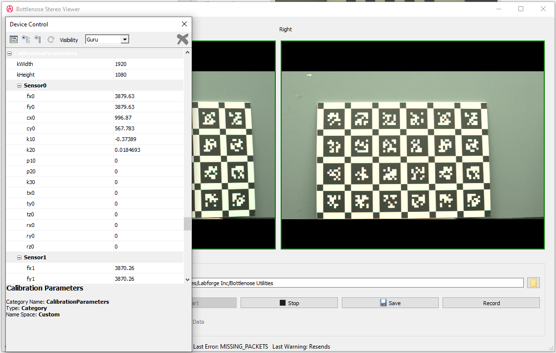
A screenshot of the calibration parameters available when using Stereo Viewer.
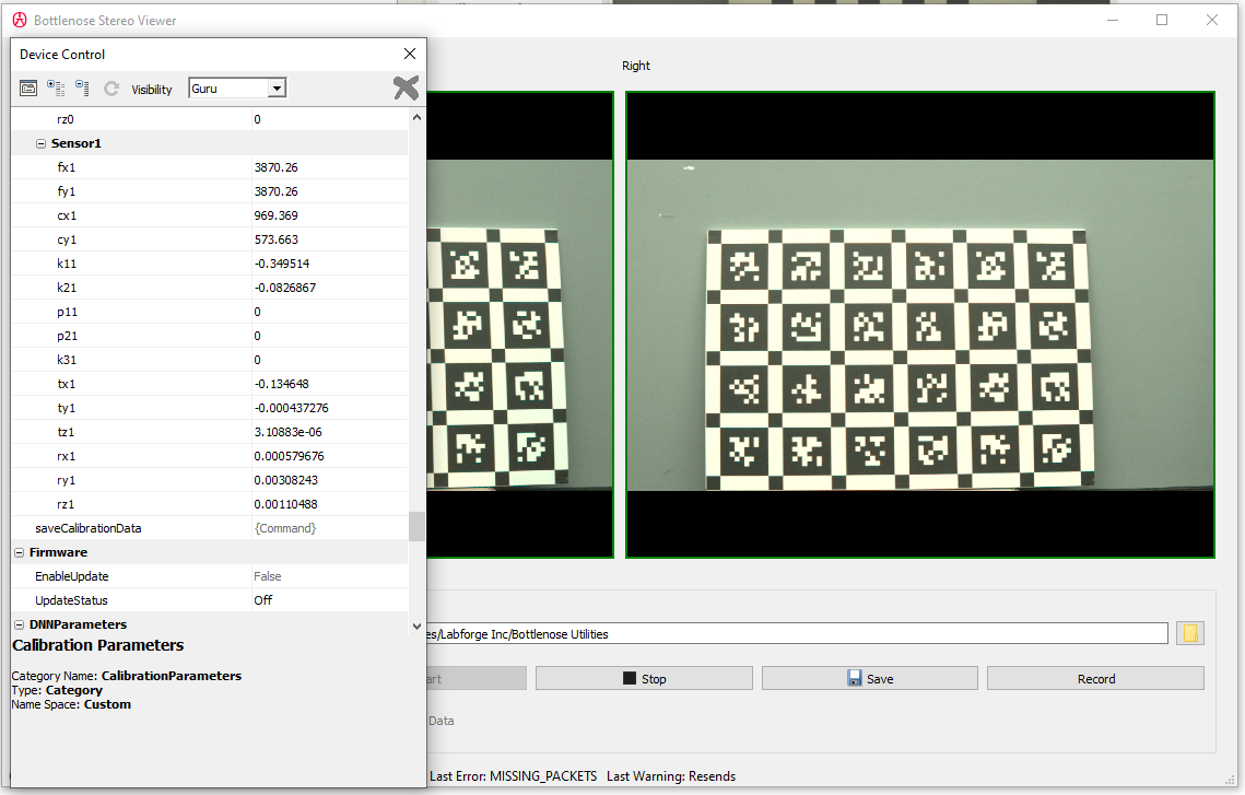
A screenshot of Stereo Viewer showing the Bottlenose calibration parameters with the saveCalibrationData button.
Manually setting calibration parameters is tedious and error-prone. Therefore, we recommend one of the following options.
Uploading Parameters with Bottlenose FileManager
The file utility can be used to transfer calibration data into a Bottlenose camera. This utility currently supports the calib.io format, the Kalibr format with only the Pinhole model and a Bottlenose format. The Bottlenose format is a YAML format with each camera node containing the following fields and limits.
- fx: the horizontal focal length
[128, 16384] - fy: the vertical focal length
[128, 16384] - cx: the horizontal principal point
[0, 4095] - cy: the vertical principal point
[0, 4095] - k1: the radial distortion parameters k1
[-8,8] - k2: the radial distortion parameters k2
[-2,2] - k3: the radial distortion parameters k3
[-0.5, 0.5] - p1: the tangential distortion parameters p1
[-16,16] - p2: the tangential distortion parameters p2
[-16,16] - tvec: The relative translation vector specified as (tx, ty, tz)
[-200, 200] - rvec: the relative rotation vector specified as (rx, ry, rz)
[-360, 360] - width: the calibrated image width
[~,3840] - height : the calibrated image height
[~,2160]
Parameters k2, k3, p1, p2 are optional and default to zero. Also, tvec and rvec can be omitted when all components are zeros.Should your calibration fall outside the limits of these parameters please revisit your calibration approach and ensure sufficient calibration target coverage in your calibration image set that is used with your calibration tool. You can use this gist to show the impact of various distortion parameters in the image plane; possibly highlighting areas of insufficient calibration target coverage.
The following shows an example calibration file for a stereo Bottlenose camera using the Bottlenose format.
cam0:
 fx: 3904.4530568689895
 fy: 3904.4530568689895

 cx: 946.7988764102324
 cy: 588.4309228593847
 k1: -0.363362245492352
 k2: 0.09269370243126594

 tvec: [0.0, 0.0, 0.0]
 rvec: [0.0, 0.0, 0.0]
 width: 1920
 height: 1080

cam1:
 fx: 3893.5546545868598
 fy: 3893.5546545868598

 cx: 898.6983669992299
 cy: 592.9350163480665

 k1: -0.36544702871726417
 k2: 0.0960047609561883

 tvec: [-0.1344377295778266, -0.0005090883806515279, 0.0006908678787488381]
 rvec: [0.0009521601234810843, 0.0057197687376942299, 0.0013624157805518208]
 width: 1920
 height: 1080
To upload a supported calibration file into a Bottlenose camera,
- Start the utility if it is not running yet.
- Click the
Selectbutton to connect to your Bottlenose camera - Set the Transfer type to Calibration
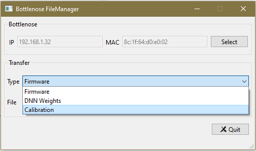
Bottlenose utility Calibration file transfer
- Click the folder button to select your calibration file. You can also choose to drag and drop the file inside the file text box.
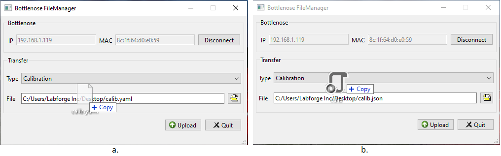
Bottlenose file utility dropping calibration file for upload: a) Labforge YAML file example, b) Example showing the calibration file produced by the calib.io tool.
- Click Upload and wait for confirmation.
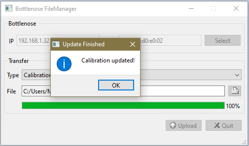
Bottlenose calibration was successfully updated.
- Quit the application when done.
Please note that this does not set theOffsetY1parameter. You still have to set this parameter separately for calibration to be valid.
Uploading Parameters with ROS2
Bottlenose provides a ROS2 driver to interact with your camera. This driver can be used to upload calibration parameters to the camera. For this, you will place your camera calibration files into the configuration folder of the ROS2 driver.
When you start your ROS2 node, for instance with the following command, the ROS driver will start and look for the calibration files inside your /config folder and load them.
ros2 run bottlenose_camera_driver bottlenose_camera_driver_node --ros-args \
     -p mac_address:="<MAC>" -p stereo:=true -p OffsetY1:=<offset used during calibration>
In ROS, a camera calibration file is a YAML file described as a ROS CameraInfo. For a stereo Bottlenose, there should be a left_camera.yaml for the left camera and a right_camera.yaml for the right camera.
The ROS calibration file for Bottlenose should have the following fields set:
- image_width: the calibrated image width
- image_height : the calibrated image height
- camera_name: the name of the camera;
left_camerafor the left file andright_camerafor the right file. - camera_matrix: the 3x3 camera matrix with the data field defined as
[fx, 0.0, cx, 0.0, fy, cy, 0.0, 0.0, 1.0] - distortion_model: the camera distortion model. Only
plumb_bobis supported. - distortion_coefficients: the 1x5 vector of distortion coefficients with its data field defined as
[k1, k2, p1, p2, k3]. - rectification_matrix: the 3x3 rectification matrix. This should always be set to identity. Bottlenose recomputes its rectification matrix using camera intrinsic and extrinsic parameters directly. For this purpose, the camera needs to know the rotation and translation vectors of each camera. We can communicate this information using the projection matrix.
- projection_matrix: the 3x4 projection matrix. This field is used to communicate the rotation and translation vectors to the camera. The data field is defined by the equation
P = K[R|t], wherePis the projection matrix,Kis the camera matrix obtained after calibration as defined above,Ris the camera rotation matrix obtained from calibration, andtthe camera translation vector. The ROS2 driver provides a sample Python code to generate this projection matrix. Please, modify the sample code to refer to your own calibration parameters.
Following are examples left and right ROS2 calibration files for a stereo Bottlenose camera.
image_width: 1920
image_height: 1080
camera_name: left_camera

camera_matrix:
  rows: 3
  cols: 3
  data: [3882.043744879964, 0.000000, 940.8649638104075, 0.000000, 3882.043744879964, 739.0978194570186, 0.000000, 0.000000, 1.000000]

distortion_model: plumb_bob
distortion_coefficients:
  rows: 1
  cols: 5
  data: [-0.3773450212923385, 0.1220120108685656, 0.0, 0.0, 0.000000]

rectification_matrix:
  rows: 3
  cols: 3
  data: [1.000000, 0.000000, 0.000000, 0.000000, 1.000000, 0.000000, 0.000000, 0.000000, 1.000000]

projection_matrix:
  rows: 3
  cols: 4
data: [3882.04374488, 0.00, 940.86496381, 0.00, 0.00, 3882.04374488, 739.09781946, 0.00, 0.00, 0.00, 1.00, 0.00]image_width: 1920
image_height: 1080
camera_name: right_camera
camera_matrix:
rows: 3
cols: 3
data: [3873.73090101178, 0.000000, 947.8880204745067, 0.000000, 3873.73090101178, 732.7951524137853, 0.000000, 0.000000, 1.000000]
distortion_model: plumb_bob
distortion_coefficients:
rows: 1
cols: 5
data: [-0.3476336920960006, -0.12108253300026231, 0.0, 0.0, 0.000000]
rectification_matrix:
rows: 3
cols: 3
data: [1.000000, 0.000000, 0.000000, 0.000000, 1.000000, 0.000000, 0.000000, 0.000000, 1.000000]
projection_matrix:
rows: 3
cols: 4
data: [3867.00032153, -6.51159055, 974.9609763, -510.65632386, -0.1278358, 3872.58669014, 738.81806954, 6.63123001, -0.00699716, -0.0015506, 0.99997432, 0.01102846]
Make sure to set theOffsetY1parameter to the value used during calibration.
Uploading Parameters with Python
It's easy to upload calibration parameters onto the camera from Python. Check our sample code repository for details on how to do this.
Updated 8 months ago